


Simulating High-Side Bootstrap Circuits With LTSpice
LTSpice is a tool that every electronics nerd should have at least a basic knowledge of. Those of us who work professionally in the analog and power worlds rely heavily …read more


LTSpice is a tool that every electronics nerd should have at least a basic knowledge of. Those of us who work professionally in the analog and power worlds rely heavily on the validity of our simulations. It’s one of the basic skills taught at college, and essential to truly understand how a circuit behaves. [Mano] has quite a collection of videos about the tool, and here is a great video explanation of how a bootstrap circuit works, enabling a high-side driver to work in the context of driving a simple buck converter. However, before understanding what a bootstrap is, we need to talk a little theory.
Bootstrap circuits are very common when NMOS (or NPN) devices are used on the high side of a switching circuit, such as a half-bridge (and by extension, a full bridge) used to drive a motor or pump current into a power supply.
From a simplistic viewpoint, due to the apparent symmetry, you’d want to have an NMOS device at the bottom and expect a PMOS device to be at the top. However, PMOS and PNP devices are weaker, rarer and more expensive than NMOS, which is all down to the device physics; simply put, the hole mobility in silicon and most other semiconductors is much lower than the electron mobility, which results in much less current. Hence, NMOS and NPN are predominant in power circuits.
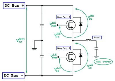
As some will be aware, to drive a high-side switching transistor, such as an NPN bipolar or an NMOS device, the source end will not be at ground, but will be tied to the switching node, which for a power supply is the output voltage. You need a way to drive the gate voltage in excess of the source or emitter end by at least the threshold voltage. This is necessary to get the device to fully turn on, to give the lowest resistance, and to cause the least power dissipation. But how do you get from the logic-level PWM control waveform to what the gate needs to switch correctly?
The answer is to use a so-called bootstrap capacitor. The idea is simple enough: during one half of the driving waveform, the capacitor is charged to some fixed voltage with respect to ground, since one end of the capacitor will be grounded periodically. On the other half cycle, the previously grounded end, jumps up to the output voltage (the source end of the high side transistor) which boosts the other side of the capacitor in excess of the source (because it got charged already) providing a temporary high-voltage floating supply than can be used to drive the high-side gate, and reliably switch on the transistor. [Mano] explains it much better in a practical scenario in the video below, but now you get the why and how of the technique.
We see videos about LTSpice quite a bit, like this excellent YouTube resource by [FesZ] for starters.