


How to Design a Weave Pattern Using 3D CAD Software
How to Design a Weave Pattern Using 3D CAD Software Weave patterns are an essential element in textile and surface design, known for their rhythmic interlacing of strands that create both visual interest and structural integrity. Translating this complex, overlapping structure into a 3D model can deepen one’s understanding of geometry, spacing, and repetition. With SelfCAD’s intuitive interface and precise modeling tools, users can simulate realistic weave patterns by carefully constructing and aligning cylindrical or ribbon-like shapes. This type of project not only strengthens spatial awareness, but also teaches the importance of symmetry, layering, and depth in digital design. In this article, we will explore how to design a basic weave pattern using SelfCAD’s features such as the move, rotate, and align tools. The process will begin with creating a single strand and duplicating it across a grid to form the over-under structure typical of woven materials. Through step-by-step guidance, readers will gain insight into pattern creation and how to maintain consistency and realism in 3D form. Whether you're aiming to simulate fabric, basketry, or decorative surfaces, this project offers a creative and technical challenge for any aspiring 3D modeler. To access the interactive tutorial to this article, check out; https://www.selfcad.com/tutorials/3f6bw421wn286uj1dh4i6j2j1h31v4e4x295 Once you’ve launched the editor; From the drawing category on the toolbar choose freehand; From the tool panel choose rectangle; Set snap to grid vertices to true, Click on highlighted point to draw rectangle Click on highlighted point to draw rectangle Type in 20 value into the width measurement; Click on highlighted point to draw rectangle From the tool panel choose line; Click on highlighted point to draw edge Type in 20 value into the length measurement; Click on highlighted point to draw edge Click on highlighted point to draw edge Type in 20 value into the length measurement; Click on highlighted point to draw edge Click to finalize freehand drawing, which then results to; From the tools category on the toolbar choose copy offsets; Set x to 100, amount of copies to 5, Click copy button to create copies. Click ‘x’ to close copy offsets panel From the utilities category on the toolbar choose combine; Set method to merge Click to finalize combine Click copy button to copy selected objects Click rotate on the toolbar; Set y to 180, z to 180 Click ‘x’ to close transformation panel Click move on the toolbar; Set move mode to moveby, x to 50 Click ‘x’ to close transformation panel From the 3D Shapes category on the toolbar choose cube; Set width to 50, height to 20, depth to 20, position x to 325, position z to -10 Tick the checkmark finalize cube Click on drawing 1(6), drawing 1 to select it Click stitch & scoop on the toolbar; From the tool panel choose union. Tick the checkmark to finalize union Click rotate on the toolbar; Set x to 270. Click ‘x’ to close transformation panel Click move on the toolbar; Set x to 0, z to 250 Click ‘x’ to close transformation panel From the tools category on the toolbar choose copy offsets; Set z to -50, Click add option to add next macro step; Set operation to rotate, x to 180, amount of copies to 10 Click copy button to create copies. Click copy button to copy selected objects; Click rotate on the toolbar; Set y to 90, z to 180 Click ‘x’ to close transformation panel From the edit menu on the top toolbar click select all From the utilities category on the toolbar choose combine; Set method to merge Click to finalize combine From the modify category on the toolbar choose resolution; Set detail level to 0 Click to finalize resolution As you continue honing your design skills, remember that SelfCAD offers a wealth of resources to support your learning journey. To deepen your understanding and explore more advanced features, consider checking out the interactive tutorials (https://www.selfcad.com/tutorials) available on the SelfCAD website. The tutorials page provides a treasure trove of guides, tips, and tricks that cater to designers of all levels. More structured learning experience can also be accessed at the SelfCAD Academy (https://www.selfcad.com/academy/curriculum/), https://www.youtube.com/@3dmodeling101, and 3D Modeling 101 series (https://www.youtube.com/playlist?list=PL74nFNT8yS9DcE1UlUUdiR1wFGv9DDfTB). This comprehensive resource offers in-depth courses taught by industry experts, allowing you to master the intricacies of SelfCAD at your own pace

How to Design a Weave Pattern Using 3D CAD Software
Weave patterns are an essential element in textile and surface design, known for their rhythmic interlacing of strands that create both visual interest and structural integrity. Translating this complex, overlapping structure into a 3D model can deepen one’s understanding of geometry, spacing, and repetition. With SelfCAD’s intuitive interface and precise modeling tools, users can simulate realistic weave patterns by carefully constructing and aligning cylindrical or ribbon-like shapes. This type of project not only strengthens spatial awareness, but also teaches the importance of symmetry, layering, and depth in digital design.
In this article, we will explore how to design a basic weave pattern using SelfCAD’s features such as the move, rotate, and align tools. The process will begin with creating a single strand and duplicating it across a grid to form the over-under structure typical of woven materials. Through step-by-step guidance, readers will gain insight into pattern creation and how to maintain consistency and realism in 3D form. Whether you're aiming to simulate fabric, basketry, or decorative surfaces, this project offers a creative and technical challenge for any aspiring 3D modeler.
To access the interactive tutorial to this article, check out; https://www.selfcad.com/tutorials/3f6bw421wn286uj1dh4i6j2j1h31v4e4x295
Once you’ve launched the editor;
From the drawing category on the toolbar choose freehand; From the tool panel choose rectangle; Set snap to grid vertices to true, Click on highlighted point to draw rectangle
Click on highlighted point to draw rectangle

Type in 20 value into the width measurement; Click on highlighted point to draw rectangle

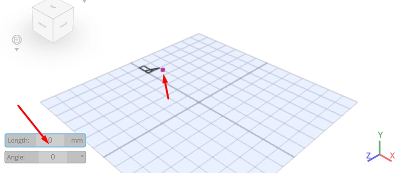
From the tool panel choose line; Click on highlighted point to draw edge

Type in 20 value into the length measurement; Click on highlighted point to draw edge

Click on highlighted point to draw edge

Type in 20 value into the length measurement; Click on highlighted point to draw edge
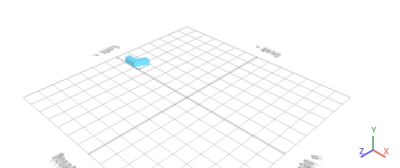
Click to finalize freehand drawing, which then results to;
From the tools category on the toolbar choose copy offsets; Set x to 100, amount of copies to 5, Click copy button to create copies.
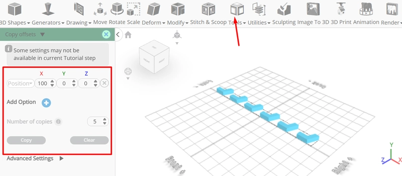
Click ‘x’ to close copy offsets panel
From the utilities category on the toolbar choose combine; Set method to merge

Click to finalize combine
Click copy button to copy selected objects
Click rotate on the toolbar; Set y to 180, z to 180

Click ‘x’ to close transformation panel
Click move on the toolbar; Set move mode to moveby, x to 50

Click ‘x’ to close transformation panel
From the 3D Shapes category on the toolbar choose cube; Set width to 50, height to 20, depth to 20, position x to 325, position z to -10

Tick the checkmark finalize cube
Click on drawing 1(6), drawing 1 to select it
Click stitch & scoop on the toolbar; From the tool panel choose union.

Tick the checkmark to finalize union
Click rotate on the toolbar; Set x to 270.

Click ‘x’ to close transformation panel
Click move on the toolbar; Set x to 0, z to 250

Click ‘x’ to close transformation panel
From the tools category on the toolbar choose copy offsets; Set z to -50, Click add option to add next macro step; Set operation to rotate, x to 180, amount of copies to 10

Click copy button to create copies.
Click copy button to copy selected objects; Click rotate on the toolbar; Set y to 90, z to 180

Click ‘x’ to close transformation panel
From the edit menu on the top toolbar click select all
From the utilities category on the toolbar choose combine; Set method to merge

Click to finalize combine
From the modify category on the toolbar choose resolution; Set detail level to 0

Click to finalize resolution
As you continue honing your design skills, remember that SelfCAD offers a wealth of resources to support your learning journey. To deepen your understanding and explore more advanced features, consider checking out the interactive tutorials (https://www.selfcad.com/tutorials) available on the SelfCAD website. The tutorials page provides a treasure trove of guides, tips, and tricks that cater to designers of all levels.
More structured learning experience can also be accessed at the SelfCAD Academy (https://www.selfcad.com/academy/curriculum/), https://www.youtube.com/@3dmodeling101, and 3D Modeling 101 series (https://www.youtube.com/playlist?list=PL74nFNT8yS9DcE1UlUUdiR1wFGv9DDfTB). This comprehensive resource offers in-depth courses taught by industry experts, allowing you to master the intricacies of SelfCAD at your own pace