


From Zero to EKS and Hybrid-Nodes — Part 1: The VPC and VPN configuration.
In this post, I’ll walk you through how to create an Amazon EKS node running Kubernetes 1.32 and set up a Site-to-Site VPN to connect an on-prem virtual machine to your EKS cluster using Linux hybrid nodes. To complete the setup, we’ll deploy a Network Load Balancer (NLB) and an NGINX Ingress controller to manage traffic across both cloud-based and on-prem applications. The goal is to demonstrate how we can extend our on-prem infrastructure into EKS, enabling a seamless hybrid environment. This approach is especially useful in scenarios where you want to leverage local GPU machines for LLM workloads, or manage CDN nodes running on data center hardware while orchestrating everything through Kubernetes. Create VPC We’ll start by creating the VPC, which is quite straightforward using OpenTofu (formerly Terraform). Below is the configuration using the terraform-aws-modules/vpc/aws module: module "vpc" { source = "terraform-aws-modules/vpc/aws" version = "5.19.0" name = local.name #my-eks-cluster cidr = local.vpc_cidr #10.0.0.0/16 azs = local.azs #["us-east-1a", "us-east-1b", "us-east-1c"] private_subnets = [for k, v in local.azs : cidrsubnet(local.vpc_cidr, 4, k)] public_subnets = [for k, v in local.azs : cidrsubnet(local.vpc_cidr, 8, k + 48)] intra_subnets = [for k, v in local.azs : cidrsubnet(local.vpc_cidr, 8, k + 52)] enable_nat_gateway = true single_nat_gateway = true public_subnet_tags = { "kubernetes.io/role/elb" = 1 } private_subnet_tags = { "kubernetes.io/role/internal-elb" = 1 "karpenter.sh/discovery" = local.name } tags = local.tags } To apply the changes, run: tofu apply Once applied, you should see an output similar to the following: This setup creates a basic but functional VPC with three subnet types, each serving a specific purpose: Private Subnets: Used for deploying nodes and pods. Public Subnets: Used for exposing services via Network Load Balancers. Intra Subnets: Dedicated to the EKS control plane. In the next steps, we’ll manually configure routing and VPN components. I’m choosing not to automate those with Terraform to better explain each concept and step in detail. VPN Site to Site: As you could see in the infra diagram, the local network CIDR is 192.168.100.0/23 and the VPC CIDR is 10.0.0.0/16 so we need to go to each subnet in our new VPC Create the Customer gateway. First we need to create the Customer gateway, this is a very simple step, we only need to define a name (Name tag — optional) and also what is the public IP (IP address) address of our local network router (in my case the routes is in a DMZ behind a NAT) Name tag: eks-kybrid-customer-gateway IP Address: [Your public IPv4] Create the Virtual private gateway To create the Virtual Private Gateway, you only need to assign a name tag. This component will act as the gateway between your AWS VPC and the on-premises network. Name tag: eks-kybrid-private-gateway Create the Site-To-Site VPN connection Once the Customer Gateway and Virtual Private Gateway are created, we can proceed to establish the Site-to-Site VPN connection. In this step, we will configure the following settings: Name tag: eks-kybrid-vpn Target gateway type: Virtual Private Gateway (select the one created earlier) Customer gateway: Existing (select the previously created Customer Gateway) Routing options: Static Static IP prefixes: 192.168.100.0/23 (your on-prem network) Local IPv4 network CIDR: 192.168.100.0/23 (your on-prem network) Remote IPv4 network CIDR: 10.0.0.0/16 (the VPC CIDR) This configuration defines the routing paths for traffic between your on-premises network and the EKS cluster running in the cloud. Attach the Virtual private gateway to VPC In this step, we will attach the previously created private gateway to our EKS VPC. This connection allows the VPC to establish communication with the on-premises network through the Site-to-Site VPN. Setup Routes in VPC. To enable communication between resources in our VPC and the on-premises network, we need to update the routing tables. This configuration ensures that traffic destined for the local network is directed through the private gateway. We will update each of the relevant route tables: private, public, and intra, by adding a route to the local CIDR block 192.168.100.0/23 with the Private Gateway as the target. Configure the client. Now that everything is set up on the AWS side, it’s time to configure the VPN client on your local environment. In my case, the client is a Ubuntu 24.04 virtual machine located in a DMZ, meaning any request sent to my public IP is forwarded to this machine. We’ll be using Strongswan as the VPN client to connect to AWS’s Site-to-Site VPN. Step 1: Download the VPN Configuration Go to the VPC Dashboard → Site-to-Site VPN Connections, select your VPN
In this post, I’ll walk you through how to create an Amazon EKS node running Kubernetes 1.32 and set up a Site-to-Site VPN to connect an on-prem virtual machine to your EKS cluster using Linux hybrid nodes. To complete the setup, we’ll deploy a Network Load Balancer (NLB) and an NGINX Ingress controller to manage traffic across both cloud-based and on-prem applications.
The goal is to demonstrate how we can extend our on-prem infrastructure into EKS, enabling a seamless hybrid environment. This approach is especially useful in scenarios where you want to leverage local GPU machines for LLM workloads, or manage CDN nodes running on data center hardware while orchestrating everything through Kubernetes.
Create VPC
We’ll start by creating the VPC, which is quite straightforward using OpenTofu (formerly Terraform). Below is the configuration using the terraform-aws-modules/vpc/aws module:
module "vpc" {
  source  = "terraform-aws-modules/vpc/aws"
  version = "5.19.0"

  name = local.name #my-eks-cluster
  cidr = local.vpc_cidr #10.0.0.0/16

  azs             = local.azs #["us-east-1a", "us-east-1b", "us-east-1c"]
  private_subnets = [for k, v in local.azs : cidrsubnet(local.vpc_cidr, 4, k)]
  public_subnets  = [for k, v in local.azs : cidrsubnet(local.vpc_cidr, 8, k + 48)]
  intra_subnets   = [for k, v in local.azs : cidrsubnet(local.vpc_cidr, 8, k + 52)]

  enable_nat_gateway = true
  single_nat_gateway = true

  public_subnet_tags = {
    "kubernetes.io/role/elb" = 1
  }

  private_subnet_tags = {
    "kubernetes.io/role/internal-elb" = 1
    "karpenter.sh/discovery" = local.name
  }

  tags = local.tags
}
To apply the changes, run:
tofu apply
Once applied, you should see an output similar to the following:
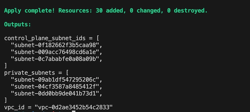
This setup creates a basic but functional VPC with three subnet types, each serving a specific purpose:
- Private Subnets: Used for deploying nodes and pods.
- Public Subnets: Used for exposing services via Network Load Balancers.
- Intra Subnets: Dedicated to the EKS control plane. In the next steps, we’ll manually configure routing and VPN components. I’m choosing not to automate those with Terraform to better explain each concept and step in detail.
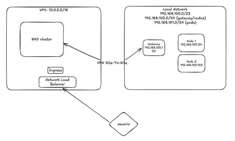
VPN Site to Site:
As you could see in the infra diagram, the local network CIDR is 192.168.100.0/23 and the VPC CIDR is 10.0.0.0/16 so we need to go to each subnet in our new VPC
Create the Customer gateway.
First we need to create the Customer gateway, this is a very simple step, we only need to define a name (Name tag — optional) and also what is the public IP (IP address) address of our local network router (in my case the routes is in a DMZ behind a NAT)
Name tag: eks-kybrid-customer-gateway
IP Address: [Your public IPv4]
Create the Virtual private gateway
To create the Virtual Private Gateway, you only need to assign a name tag. This component will act as the gateway between your AWS VPC and the on-premises network.
Name tag: eks-kybrid-private-gateway
Create the Site-To-Site VPN connection
Once the Customer Gateway and Virtual Private Gateway are created, we can proceed to establish the Site-to-Site VPN connection.
In this step, we will configure the following settings:
Name tag: eks-kybrid-vpn
Target gateway type: Virtual Private Gateway (select the one created earlier)
Customer gateway: Existing (select the previously created Customer Gateway)
Routing options: Static
Static IP prefixes: 192.168.100.0/23 (your on-prem network)
Local IPv4 network CIDR: 192.168.100.0/23 (your on-prem network)
Remote IPv4 network CIDR: 10.0.0.0/16 (the VPC CIDR)
This configuration defines the routing paths for traffic between your on-premises network and the EKS cluster running in the cloud.
Attach the Virtual private gateway to VPC
In this step, we will attach the previously created private gateway to our EKS VPC. This connection allows the VPC to establish communication with the on-premises network through the Site-to-Site VPN.
Setup Routes in VPC.
To enable communication between resources in our VPC and the on-premises network, we need to update the routing tables. This configuration ensures that traffic destined for the local network is directed through the private gateway.
We will update each of the relevant route tables: private, public, and intra, by adding a route to the local CIDR block 192.168.100.0/23 with the Private Gateway as the target.
Configure the client.
Now that everything is set up on the AWS side, it’s time to configure the VPN client on your local environment.
In my case, the client is a Ubuntu 24.04 virtual machine located in a DMZ, meaning any request sent to my public IP is forwarded to this machine. We’ll be using Strongswan as the VPN client to connect to AWS’s Site-to-Site VPN.
Step 1: Download the VPN Configuration
Go to the VPC Dashboard → Site-to-Site VPN Connections, select your VPN connection, and click Download Configuration. Choose Strongswan as the vendor.
Step 2: Install Strongswan
On your VPN client machine, install Strongswan using:
apt update
apt install strongswan
Step 3: Configure the VPN Tunnels
Use the provided AWS configuration as a base. Edit the file /etc/ipsec.conf with your VPN tunnel definitions, updating values where needed (e.g., IP addresses, leftupdown hook). Here’s an example configuration:
config setup
        uniqueids = no

conn Tunnel1
 auto=start
 left=%defaultroute
 leftid=186.10.xx.xx
 right=34.194.25.197
 type=tunnel
 leftauth=psk
 rightauth=psk
 keyexchange=ikev1
 ike=aes128-sha1-modp1024
 ikelifetime=8h
 esp=aes128-sha1-modp1024
 lifetime=1h
 keyingtries=%forever
 leftsubnet=0.0.0.0/0
 rightsubnet=0.0.0.0/0
 dpddelay=10s
 dpdtimeout=30s
 dpdaction=restart
 mark=100
 leftupdown="/etc/ipsec.d/aws-updown.sh -ln Tunnel1 -ll 169.254.41.174/30 -lr 169.254.41.173/30 -m 100 -r 10.0.0.0/16"

conn Tunnel2
 auto=start
 left=%defaultroute
 leftid=186.10.xx.xx
 right=100.27.149.167
 type=tunnel
 leftauth=psk
 rightauth=psk
 keyexchange=ikev1
 ike=aes128-sha1-modp1024
 ikelifetime=8h
 esp=aes128-sha1-modp1024
 lifetime=1h
 keyingtries=%forever
 leftsubnet=0.0.0.0/0
 rightsubnet=0.0.0.0/0
 dpddelay=10s
 dpdtimeout=30s
 dpdaction=restart
 mark=200
 leftupdown="/etc/ipsec.d/aws-updown.sh -ln Tunnel2 -ll 169.254.125.226/30 -lr 169.254.125.225/30 -m 200 -r 10.0.0.0/16"
Step 4: Update the updown Script
The file /etc/ipsec.d/aws-updown.sh manages the VTI interface setup for each tunnel. If your VPN client is behind a NAT (like mine), you need to manually set the src IP in the routing section.
Locate the add_route() function and modify the ip route add line to include your local machine’s internal IP (192.168.100.100 in this case):
ip route add ${i} dev ${TUNNEL_NAME} metric ${TUNNEL_MARK}
Here’s the complete updown script:
#!/bin/bash

while [[ $# > 1 ]]; do
 case ${1} in
  -ln|--link-name)
   TUNNEL_NAME="${2}"
   TUNNEL_PHY_INTERFACE="${PLUTO_INTERFACE}"
   shift
   ;;
  -ll|--link-local)
   TUNNEL_LOCAL_ADDRESS="${2}"
   TUNNEL_LOCAL_ENDPOINT="${PLUTO_ME}"
   shift
   ;;
  -lr|--link-remote)
   TUNNEL_REMOTE_ADDRESS="${2}"
   TUNNEL_REMOTE_ENDPOINT="${PLUTO_PEER}"
   shift
   ;;
  -m|--mark)
   TUNNEL_MARK="${2}"
   shift
   ;;
  -r|--static-route)
   TUNNEL_STATIC_ROUTE="${2}"
   shift
   ;;
  *)
   echo "${0}: Unknown argument \"${1}\"" >&2
   ;;
 esac
 shift
done

command_exists() {
 type "$1" >&2 2>&2
}

create_interface() {
 ip link add ${TUNNEL_NAME} type vti local ${TUNNEL_LOCAL_ENDPOINT} remote ${TUNNEL_REMOTE_ENDPOINT} key ${TUNNEL_MARK}
 ip addr add ${TUNNEL_LOCAL_ADDRESS} remote ${TUNNEL_REMOTE_ADDRESS} dev ${TUNNEL_NAME}
 ip link set ${TUNNEL_NAME} up mtu 1419
}

configure_sysctl() {
 sysctl -w net.ipv4.ip_forward=1
 sysctl -w net.ipv4.conf.${TUNNEL_NAME}.rp_filter=2
 sysctl -w net.ipv4.conf.${TUNNEL_NAME}.disable_policy=1
 sysctl -w net.ipv4.conf.${TUNNEL_PHY_INTERFACE}.disable_xfrm=1
 sysctl -w net.ipv4.conf.${TUNNEL_PHY_INTERFACE}.disable_policy=1
}

add_route() {
 IFS=',' read -ra route <<< "${TUNNEL_STATIC_ROUTE}"
     for i in "${route[@]}"; do
     ip route add ${i} dev ${TUNNEL_NAME} metric ${TUNNEL_MARK} src 192.168.100.100
 done
 iptables -t mangle -A FORWARD -o ${TUNNEL_NAME} -p tcp --tcp-flags SYN,RST SYN -j TCPMSS --clamp-mss-to-pmtu
 iptables -t mangle -A INPUT -p esp -s ${TUNNEL_REMOTE_ENDPOINT} -d ${TUNNEL_LOCAL_ENDPOINT} -j MARK --set-xmark ${TUNNEL_MARK}
 ip route flush table 220
}

cleanup() {
        IFS=',' read -ra route <<< "${TUNNEL_STATIC_ROUTE}"
        for i in "${route[@]}"; do
            ip route del ${i} dev ${TUNNEL_NAME} metric ${TUNNEL_MARK}
        done
 iptables -t mangle -D FORWARD -o ${TUNNEL_NAME} -p tcp --tcp-flags SYN,RST SYN -j TCPMSS --clamp-mss-to-pmtu
 iptables -t mangle -D INPUT -p esp -s ${TUNNEL_REMOTE_ENDPOINT} -d ${TUNNEL_LOCAL_ENDPOINT} -j MARK --set-xmark ${TUNNEL_MARK}
 ip route flush cache
}

delete_interface() {
 ip link set ${TUNNEL_NAME} down
 ip link del ${TUNNEL_NAME}
}

# main execution starts here

command_exists ip || echo "ERROR: ip command is required to execute the script, check if you are running as root, mostly to do with path, /sbin/" >&2 2>&2
command_exists iptables || echo "ERROR: iptables command is required to execute the script, check if you are running as root, mostly to do with path, /sbin/" >&2 2>&2
command_exists sysctl || echo "ERROR: sysctl command is required to execute the script, check if you are running as root, mostly to do with path, /sbin/" >&2 2>&2

case "${PLUTO_VERB}" in
 up-client)
  create_interface
  configure_sysctl
  add_route
  ;;
 down-client)
  cleanup
  delete_interface
  ;;
esac
Step 5: Add Shared Secrets
Open /etc/ipsec.secrets and add the shared secrets provided in the configuration file:
# This file holds shared secrets or RSA private keys for authentication.

# RSA private key for this host, authenticating it to any other host
# which knows the public part.

186.10.xx.xx 34.194.25.197 : PSK "kPcU.tJ_sA33J7Z.I4f4gxxxxx"
186.10.xx.xx 100.27.149.167 : PSK "YtaQSGhvMKV4aLQx.4wxxxxxxx"
Step 6: Start the VPN Service
Restart the service and check the tunnel status:
systemctl restart ipsec
ipsec status
The following video demonstrates the complete setup step by step:
If everything is correctly configured, both tunnels should show as “up” in the AWS Console → Site-to-Site VPN Connections page.
At this stage, the network connectivity between the EKS cluster and the on-premises environment is fully configured:
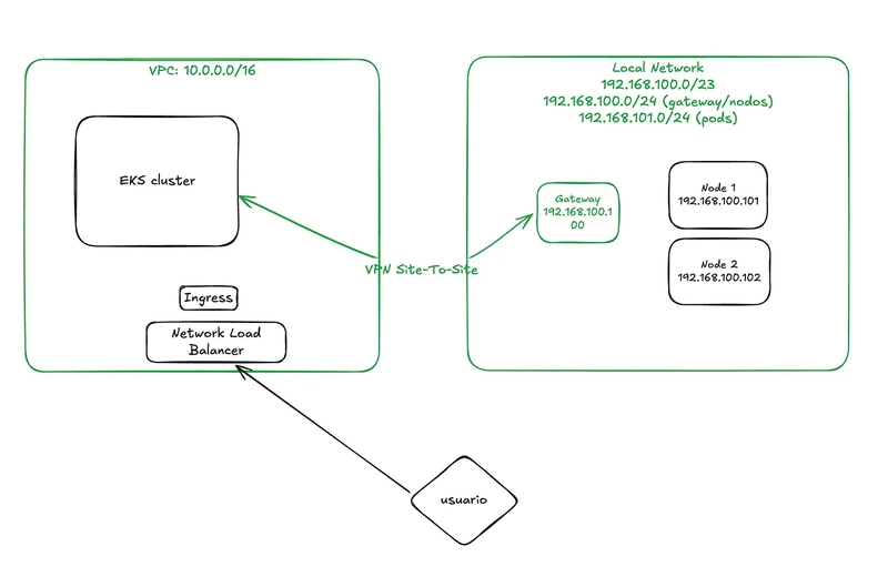
In Part 2, we will provision the EKS cluster using OpenTofu, set up the SSM activator, and register the on-premises nodes using nodeadm with the Cilium CNI driver.
In Part 3, we will install the AWS Load Balancer Controller, configure NGINX Ingress, and deploy our application across both EC2 and hybrid (on-prem) nodes.