


_Brian_Jackson_Alamy.jpg?width=1280&auto=webp&quality=80&disable=upscale#)


How to Design a Traditional Windmill Using 3D CAD Software
How to Design a Traditional Windmill Using 3D CAD Software Traditional windmills, with their tall towers and iconic rotating blades, have long stood as symbols of rural engineering and sustainable energy. Recreating these classic structures in 3D can be both a rewarding artistic challenge and a practical way to build modeling skills. Using SelfCAD, a web-based 3D modeling program that balances ease of use with powerful design tools, users can construct a detailed digital version of a traditional windmill from the ground up. This includes modeling key architectural features like the base tower, cap, and of course, the sails, which require precision and symmetry. This article will guide readers through the process of designing a traditional windmill in SelfCAD, starting with basic geometric shapes and moving into more advanced features such as face selection, object grouping, and rotation tools. Each step will demonstrate how to bring historical design elements to life in a digital environment. Whether you're a beginner experimenting with architectural modeling or a student working on a historical project, designing a windmill in SelfCAD offers a hands-on way to explore both 3D design and engineering heritage. To access the interactive tutorial to this article, check out; https://www.selfcad.com/tutorials/5p6k2ll145x2b6n1k71435yz6r1c3i1k4j2j Once you’ve launched the editor; From the generators category on the toolbar choose shape generator; Set top radius to 150, bottom radius to 150, number of edges to 20, height to 40 Click + button to add new segment; Set top radius to 170, bottom radius to 170, height to 20 Click + button to add new segment; Set top radius to 150, bottom radius to 150, height to 343 Click + button to add new segment; Set top radius to 175 Click + button to add new segment; Set top radius to 12, height to 140 Tick the checkmark to finalize shape generator Click solid+wireframe button to set rendering mode From the modify category on the toolbar choose edit details; Set loop finding to true, Drag highlighted edge to highlighted line to add edge loop Click to finalize edit details Click to activate face selection; Click on highlighted region to select it From the modify category on the toolbar choose extrusion; Set extrusion amount to 44 Tick the checkmark to finalize extrusion Click on highlighted region to deselect it From the 3D Shapes category on the toolbar choose cylinder; Set top radius to 26, Bottom radius to 26, horizontal segments to 6, vertical segments to 8, position x to 24, position y to 346, position z to 189, rotation x to 90, rotation z to -5 Tick the checkmark to finalize cylinder Click on highlighted region to select it From the modify category on the toolbar choose extrusion; Set is individual to true, extrusion amount to 50 Click add option to add next macro step; Set operation to inset; amount to 3 Click add option to add next macro step; Set operation to extrusion; amount to 200 Tick the checkmark to finalize extrusion, Click on highlighted region to deselect it Click on highlighted region to select it From the modify category on the toolbar choose inset; Set is individual to true, inset amount to 3 Click add option to add next macro step; Set operation to extrusion; amount to 40. Tick the checkmark to finalize inset Click on highlighted region to deselect it Click to activate edge selection; Click on highlighted region to select it From the modify category on the toolbar click chamfer; Set intensity to 2 Click to finalize chamfer Click highlighted part on selection cube to turn off region selection From the modify category on the toolbar choose add thickness; Set thickness to -6. Tick the checkmark to finalize add thickness As you continue honing your design skills, remember that SelfCAD offers a wealth of resources to support your learning journey. To deepen your understanding and explore more advanced features, consider checking out the interactive tutorials (https://www.selfcad.com/tutorials) available on the SelfCAD website. The tutorials page provides a treasure trove of guides, tips, and tricks that cater to designers of all levels. More structured learning experience can also be accessed at the SelfCAD Academy (https://www.selfcad.com/academy/curriculum/), https://www.youtube.com/@3dmodeling101, and 3D Modeling 101 series (https://www.youtube.com/playlist?list=PL74nFNT8yS9DcE1UlUUdiR1wFGv9DDfTB). This comprehensive resource offers in-depth courses taught by industry experts, allowing you to master the intricacies of SelfCAD at your own pace

How to Design a Traditional Windmill Using 3D CAD Software
Traditional windmills, with their tall towers and iconic rotating blades, have long stood as symbols of rural engineering and sustainable energy. Recreating these classic structures in 3D can be both a rewarding artistic challenge and a practical way to build modeling skills. Using SelfCAD, a web-based 3D modeling program that balances ease of use with powerful design tools, users can construct a detailed digital version of a traditional windmill from the ground up. This includes modeling key architectural features like the base tower, cap, and of course, the sails, which require precision and symmetry.
This article will guide readers through the process of designing a traditional windmill in SelfCAD, starting with basic geometric shapes and moving into more advanced features such as face selection, object grouping, and rotation tools. Each step will demonstrate how to bring historical design elements to life in a digital environment. Whether you're a beginner experimenting with architectural modeling or a student working on a historical project, designing a windmill in SelfCAD offers a hands-on way to explore both 3D design and engineering heritage.
To access the interactive tutorial to this article, check out; https://www.selfcad.com/tutorials/5p6k2ll145x2b6n1k71435yz6r1c3i1k4j2j
Once you’ve launched the editor;
From the generators category on the toolbar choose shape generator; Set top radius to 150, bottom radius to 150, number of edges to 20, height to 40
Click + button to add new segment; Set top radius to 170, bottom radius to 170, height to 20

Click + button to add new segment; Set top radius to 150, bottom radius to 150, height to 343

Click + button to add new segment; Set top radius to 175

Click + button to add new segment; Set top radius to 12, height to 140

Tick the checkmark to finalize shape generator
Click solid+wireframe button to set rendering mode
From the modify category on the toolbar choose edit details; Set loop finding to true, Drag highlighted edge to highlighted line to add edge loop

Click to finalize edit details
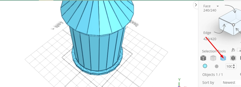
Click to activate face selection; Click on highlighted region to select it
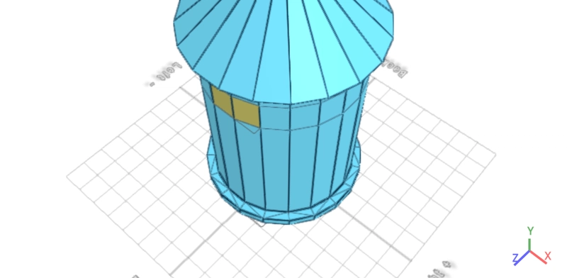
From the modify category on the toolbar choose extrusion; Set extrusion amount to 44

Tick the checkmark to finalize extrusion
Click on highlighted region to deselect it
From the 3D Shapes category on the toolbar choose cylinder; Set top radius to 26, Bottom radius to 26, horizontal segments to 6, vertical segments to 8, position x to 24, position y to 346, position z to 189, rotation x to 90, rotation z to -5
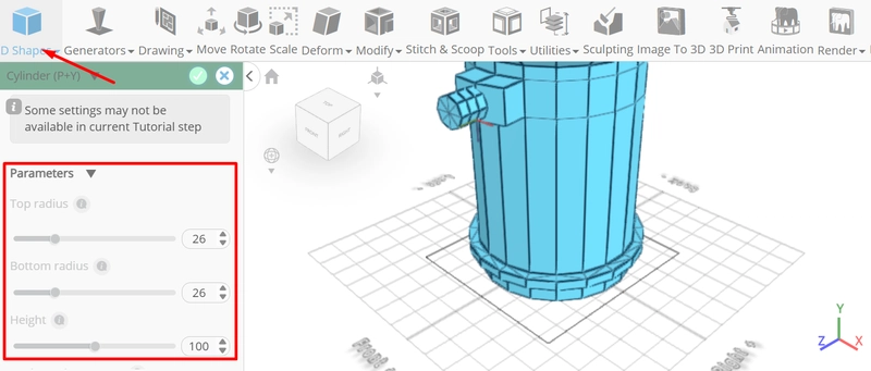
Tick the checkmark to finalize cylinder
Click on highlighted region to select it

From the modify category on the toolbar choose extrusion; Set is individual to true, extrusion amount to 50
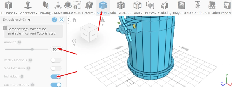
Click add option to add next macro step; Set operation to inset; amount to 3
Click add option to add next macro step; Set operation to extrusion; amount to 200

Tick the checkmark to finalize extrusion, Click on highlighted region to deselect it
Click on highlighted region to select it

From the modify category on the toolbar choose inset; Set is individual to true, inset amount to 3
Click add option to add next macro step; Set operation to extrusion; amount to 40.

Tick the checkmark to finalize inset
Click on highlighted region to deselect it
Click to activate edge selection; Click on highlighted region to select it

From the modify category on the toolbar click chamfer; Set intensity to 2

Click to finalize chamfer
Click highlighted part on selection cube to turn off region selection
From the modify category on the toolbar choose add thickness; Set thickness to -6.
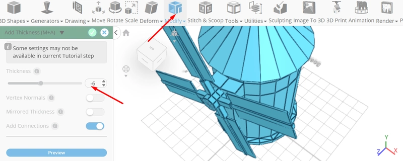
Tick the checkmark to finalize add thickness
As you continue honing your design skills, remember that SelfCAD offers a wealth of resources to support your learning journey. To deepen your understanding and explore more advanced features, consider checking out the interactive tutorials (https://www.selfcad.com/tutorials) available on the SelfCAD website. The tutorials page provides a treasure trove of guides, tips, and tricks that cater to designers of all levels.
More structured learning experience can also be accessed at the SelfCAD Academy (https://www.selfcad.com/academy/curriculum/), https://www.youtube.com/@3dmodeling101, and 3D Modeling 101 series (https://www.youtube.com/playlist?list=PL74nFNT8yS9DcE1UlUUdiR1wFGv9DDfTB). This comprehensive resource offers in-depth courses taught by industry experts, allowing you to master the intricacies of SelfCAD at your own pace


![[Boost] Agentica, Every TypeScript Developer is an AI Developer (AI function calling framework)](https://media2.dev.to/dynamic/image/width=800%2Cheight=%2Cfit=scale-down%2Cgravity=auto%2Cformat=auto/https%3A%2F%2Fdev-to-uploads.s3.amazonaws.com%2Fuploads%2Fuser%2Fprofile_image%2F901175%2Fd1a551cd-f5ae-4d4f-8dea-e5edec30b8d1.jpeg)


